Thursday, May 29, 2014

Week 9 Recap

Mechanical

During class today we scratched the tape/wheel idea and just sanded down one of the edges so that the belt would fit the wheel without any extra components. That worked really well actually! 

Jacque using the power tool to sand down the inside edge of the wheel
We also used a heat gun to morph the ends of the belt together. Here is the result!


Now we just have to go back to the machine shop to mount the base again (for proper tension) and to align the whole system properly. 

Electrical

Datasheets:

  • http://www.instructables.com/id/Wire-a-Potentiometer-as-a-Variable-Resistor/
  • https://www.sparkfun.com/datasheets/Components/LM7805.pdf
  • http://www.fairchildsemi.com/ds/LM/LM2901.pdf
  • http://www.bourns.com/pdfs/3006.pdf

Tuesday, May 27, 2014

Week 9 Outside Meeting

Mechanical Group:

Today we went to the machine shop and made some serious progress. Along with the help from the machine shop crew, we built a base for the wheel to sit in made of a wooden block donated by the shop, mounted the k'NEX base by drilling holes and holding it with zip ties, and attached the lego piece to the generator shaft by using a mold and screw. 

Here are some pictures of our progress:

The base mounted with zip ties

Close up of the base mounted with zip ties

Sarah posing with the tool used to drill the hole for the bike base

View of the whole thing!


In-Class To Do:

  • Glue in wheel
  • Attach generator to base
  • Set up belt

Electrical Group:
In-Class To Do:
  • Set up the breadboard with wires and all the pieces
  • Continue needed calculations
  • Solder etc.
  • Draw up how to attach the electronics and LEDs

Together:
Need to work on the presentation and the final paper (due next week)
The presentation will be in LeBow 240 in the Hill Conference Room

Final Paper:
  • Correct the errors and tweak until up to date (Jacque)
  • Circuitry update (Courtney & Jess)
  • Research corrections (Courtney)
Presentation:
  • 10 minute speech with 2 minute question-answer session
  • Upload slides to include:
    • Title Slide (Sarah)
    • Presentation Outline (2nd slide) (Sarah)
    • Paper in slide form (All of us with)
      • Introduction (Sarah)
      • Project Objective (Sarah)
      • Project goals and timelines (Sarah)
      • Project budget (Sarah)
      • Preexisting waterwheel and surrounding exhibit (Sarah)
      • Research (Courtney)
      • Overall design (Jacque)
      • Calculations (Jacque)
      • Mechanical & Electrical design (Courtney & Jess)
      • Results (Megan)
      • Future work (Megan)
    • Question Slide (Sarah)
    • References Slide (Courtney)

We set up a GooglePowerPoint so we each can contribute to the presentation and make modifications without having to convert from Mac to PC.

Thursday, May 22, 2014

Week 8 Recap

Mechanical Group: Jacque, Sarah, and Megan 


To have the belt fit perfectly on the wheel and not slip off, we covered the wheel in duct tape and then layered more tape on the sides where the edges of the belt would end. This worked very well! 

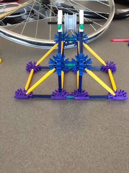
Next, we modified the base structure to be very sturdy and to have a place to put the generator. In these photos, the generator is not yet fully mounted, but will be soon with zip ties. 

Front view of base (facing the wheel head on)

Side view of base
Top view of base

View of the generator shaft and the lego piece it needs to fit


NEED TO DO: 

Visit machine shop next week and ask about suggestions on how to fit the generator shaft into the lego piece and how to mount the wheel and base to the wooden board. 


__________________________________________________


Electronics Group: Jess and Courtney 


Want LEDs to run in a parallel circuit (so that each bulb lights up at different times)

Going to first try using a current with 4 milliamps

The lights require 3 Volt batteries (9 Volts will kill the LEDs)

FROM EXPERIMENTING:
the light from the LED is discernible when it reaches 2.4 Volts and needs 4 milliamps

When the wires are connected and attached to the external power source, the total amperage reaches 12 milliamps. 


NEED TO DO:

calculate the resistor we need to get from 5Volts emitted by Voltage Regulator
(using 5 mA, 3V bulb, +/- 2V resistor)

need to look up datasheets for the 7805 

Week 8 Outside Meeting

An hour before class, we took a look at the current K'nex structure and how it fitted with the generator we ordered. We also got the wooden base for the overall prototype.


Current K'nex base as of 3:30 pm May 22, 2014
Goal for what our prototype will look like


The LED blue lights also came in yesterday (see picture). They are about 5 millimeters in size with 14-inch long wires (DC). We bought five of them just in case, but we will only really need three.


We managed to retrieve an axle from LeBow 132 that we need in the K'nex structure (as seen in the close up picture of the base).

The plan for today during class is to split up into mechanics and electronics:

  • Mechanics: 
  • Figure out how to mount the generator to the existing K'nex base
  • Fit the axle to the base
  • Mount the K'nex base to the wood
  • Electronics:
  • work on the LEDs and electronic portion of the project

Thursday, May 15, 2014

Week 7 Recap

In class today, we addressed the to do list we created from last time:


  • Choosing a set of materials for the other wheel


So we are going to use a Lego wheel - one with a radius of about 0.75 inches (0.56 inches really).

  • Get reflector off of bike wheel
Took a while, but we managed.

  • Design support base for smaller wheel
The support base is made out of basic K'nex pieces.


Top left & right: the first version of the base structure for the small Lego wheel.

Bottom left: the team working hard on building the support.


The generator has to be mounted within the vertical plane relative to the suspended Lego wheel. 
But because we do not have the generators on site with us, creating the base from the mix of Lego and K'nex pieces was impeded. The generator is about 30 mm in diameter, 48 mm (~1.75 inches) long, and with a shaft of 2.5 mm. 
Generator image from Ebay


  • Base structure
Megan and Sarah are going to go get some wood so we can construct a wooden base to hold the bike wheel and fork as well as the K'nex wheel


  • Lengths and distances for belt system

Some pictures of the small wheel with the urethane belt we received:


Top left: the bike wheel that we received from Wolf Cycles with the urethane belt.

Top right: the small Lego wheel with the urethane belt and bike wheel.

Bottom left: close-up of the Lego wheel and the urethane belt.


Thanks again to Wolf Cycles for the bike and fork!


Next:
we need to get a shaft from LeBow 132 Engineering building

Monday, May 12, 2014

Week 7 Outside Meeting

So we are still consulting with our TA, Marco. From his suggestions, our next in-class meeting will concentrate on:


  • Choosing a set of materials for the other wheels (right now we are thinking of using a K'nex wheel)
  • Get the reflector off of the bike wheel
  • Design support for smaller wheel
  • Need base structure: co-linear, vertical, and constant
  • Figure out lengths and distances for the belt system

By meeting of Week 9: the generators should be here, so then we can set them up and get the wiring and circuitry done


FINAL REPORT:
Researching Section: Courtney
Calculations Section: Jacque
Mechanical Work: Sarah and Megan
Abstract: Jess (everyone helps edit for continuity)

Email draft to Marco: Jacque


Researching LEDs:
(http://www.modeltrainsoftware.com/miniatureleds.html)

This site sells 3V blue LEDs (technically for miniature train sets, but this suits our needs). Luckily they mention on site that the parts ship next business day and cost $2.25 each.

Thursday, May 8, 2014

Week 6 Recap

Today we had to look at the big picture and make some BIG changes to our plans. 

We aren't doing a full-scale Please Touch Museum exhibit for the water wheel. Instead, we are doing a full-scale prototype model of the system of belts and pulleys that would be attached to the water wheel at the museum.

So it's week 6 and the deadline to have a physical representation of what we've been up to is a whole lot closer this side of week 5. We walked all the way down to Wolf Cycle to get bike parts. We got a 24 inch wheel -- that's actually a 19 inch rim when not counting the tire (see picture below)  and a fork to fit it. 


This bike wheel part (minus the tire) will be the giant wheel from that diagram Jacque drew in week 5's recap. Next we have to calculate out the proportions so all the other wheels will be proportional to our big 19 inch bike wheel.

We also need to order the belts and wait for the motors to get here.

Tuesday, May 6, 2014

Week 6 Outside Meeting: Researching Materials

Flat Belts

(the following information was from: http://www.gatesmectrol.com/common/downloads/files/mectrol/brochure/GatesMectrol_Belt_Pulley_Catalog_5_11.pdf )


Features:
Smooth, vibration free operation
Use with small pulley diameters
High strength, low stretch for long life
Sealed edges, no cord fraying
Easily guided with flanged pulleys
Kevlar or steel cord construction
No lubrication needed
No retensioning required

Application Characteristics:
Heavy load lifting or lowering
Allows for "slip" requirement
Smooth uniform motion
Small bending radius for small design envelope
Very low stretch characteristics


As seen from the photos, the best part about flat belts is how it can be used on a smaller scale, the make of a flat belt purposefully reduces stretching and wearing out, and can be used with pulleys with smaller diameters. The charts are helpful when we need to determine the coefficients of friction and weight etcetera when we need to decide what the flat belt's material should be.

Also, for future reference, we can use the following site:


Pulleys
Needs to be:
1. groove to keep pulley in place
2. waterproof (either waterproofed easily or already)
3. rigidity
4. machine-ability
5. light-weight
6. low maintenance
7. able to keep belt on the track with minimal outside help

http://engapps.gates.com/LinearApp/MotionCalculator/Step1 : helps to determine which belts, pulleys, and what materials would be needed based on certain input parameters


Gives a short history of how crowned pulleys were used with flat belts in addition to more information of flat belts and crowned pulley applications. 

While nowadays we use V-belts, the older technology used flat belts in combination with crowned pulleys. A crowned pulley is a pulley that has a slight hump in the middle and tapers off slightly toward either edge (as shown in the photo below).

This tapering edge helps to keep the belt on track automatically. In order to better illustrate this concept of the pulley helping the belt to stay on track, the author demonstrates with a rubber band:
"The key to understanding the flat belt tracking on a crowned pulley is to look at how a belt flexes when pulled more on one edge than another. I'm pulling the rubber band in the photo on just the right edge. With more tension on the right side, that side stretches more, and the rubber band forms a slight arch. In an actual belt, this stretch is too subtle to be seen by just looking at it.
"To better demonstrate the principle, [the author] built a jig from Lego, using a rubber band and an exaggerated crowned wooden pulley. The higher section of the crowned pulley puts more tension on the rubber band than the narrower edges. As a result, the rubber band flexes into a slight arch towards the middle. As the rubber band winds onto the pulley, this arch causes the band to always wind further up on the conical section than what was previously wound on. The higher point on the pulley always creates more tension in the belt and causes it to arch in that direction.

"With this exaggerated crowned pulley, it takes just a few turns for the rubber band to wander from the edge all the way to up the center hump. Once the rubber band is on top, the maximum tension will be in the middle of it, and it no longer has any reason to arch in either direction...With much more subtle crowning on a typical pulley, the self-centering of the belt happens more slowly." 

The following information was quoted from http://www.niba.org/index.php/resources/technical-articles/0603-crowned-pulleys/
"In order to be effective, a crowned pulley requires that the conveyor system have enough tension in it to force the belt to conform to the configuration of the pulley. Experience has also shown that a crown is most effective when it has a long unsupported span of belt approaching the pulley (3 feet plus, with little added effect over 10 feet) That is, the belt must be free of the effects of troughing idlers, rollers, slider beds, etc., for the crown to offer significant tracking advantages.
"...A crowned pulley should never be run against the coated conveying side of a lightweight belt.
"...Belts with high transverse rigidity require less slope to the face of the pulley to allow the belt to conform to the crown and influence the tracking of the belt."
 Essentially, a crowned pulley needs a lot of tension from the belt in order to actually keep the belt tracked. 
So we next had to research how to calculate the tension of the flat belt we would need.

We will be using the calculator program from http://www.niba.org/resources/belt-tension-calculator/. The math behind this calculator is clearly explained on their website.

From the site http://www.visusa.com/belt_tracking01.htm, we looked up the typical crown radius specifications when used specifically with flat belt pulleys.


Week 6 in class plan: 
1. Group: Continue discussing materials, ask for teacher opinions 
2. Courtney and Jess: discussing electronics, what we need to build or buy, how we're going to do that
3. Sarah and Megan: purchase materials for pulley and belt 
4. Jacque: design and plan to purchase materials for raindrops 

5. Group: Think about prototyping possibilities 

Thursday, May 1, 2014

Meeting with Marco / Week 5 Recap

On April 30th, I (Jacque) met with Marco (one of our advisors) to go over calculations and possibilities for generating the voltage with the available rpm the water wheel gives us without any external pumping. We have about 6 rpm to work with and a radius of 0.5 meters. We also figured in order to power one yellow or red LED we'll need at least 3 volts (the least amount required for the available colors).
One generator that we found requires 900 rpm to generate 3 volts. This can be seen here on ebay.
Using the relationship: 
ωA represents the angular velocity (rpms) for the water wheel and rA represents its radius. ωB is the angular velocity we'd get with water rB we decide to use. At first this was upsetting, figuring that for 900 rpm we'd need a final radius of 3 mm. Wowza! That seemed not very feasible, especially for the durability we're looking for, so we had to consider our options. An amplifier? That would require external power, not ideal, but it could work. Maybe use a bike dynamo? That may require too much torque/inertia, which we do not have much of. We met before class to discuss, but didn't come to any serious conclusions. 

During class, however, Dr. Scoles had the idea to do more than 1 wheel ratio. Brilliant! This means that we'd hook up the larger pulley that is attached to the water wheel to a smaller radius with a belt, and attach a larger radius to that smaller radius, so from there we could have another belt to an even smaller radius, getting an actual decent amount of rpm! Here's a sketch of what I'm trying to say: 


And with the ratios in this spread sheet, we can reach at least 900 rpm:


These ratios seem a little crazy, but we think it is definitely doable. It'll have to be! This coming week we're going to search for DC generators like the one on ebay (only issue with that one is it takes 2-3 weeks shipping! But if we have to order it from there, we will). We also have to consider materials to make the pulleys and what belts to buy. 

Other in class accomplishments: 

Jess & Courtney:
They had to calculate the mass of the existing water wheel to continue the "Background" section of the blog. We obviously needed to estimate every measurement, and most of these estimates had to come from looking closely at the photos we took from the Please Touch Museum. 

Courtney & Megan: 
They learned how the external power source operated along with a small example moter complete with working gears encased in clear plastic. The max voltage for that particular motor was 3 volts, but had been known to make it safely to 5 volts for no more than 10 seconds. Hopefully we can use this generator/motor or a similar one for our project. 

Sarah: 
She worked on the final project.